10 Best Visual Flow Indicators for Global Buyers?

Choosing the right visual flow indicator is a practical decision for global buyers. It affects process visibility, maintenance speed, and daily operating confidence. In a clear pipeline, a rotating wheel, moving paddle, or colored disc can reveal flow within seconds. That small signal may prevent a costly inspection delay.

This guide reviews 10 best visual flow indicator options for international purchasing teams. It considers viewing direction, connection type, pressure range, temperature limits, body materials, and seal performance. It also examines supplier documentation, inspection records, replacement parts, and delivery support. These details matter when equipment crosses borders and enters unfamiliar plant environments.

No ranking fits every facility. A compact acrylic model may suit water treatment, while a stainless-steel unit may better match chemical processing. However, material compatibility still requires careful verification. I have seen buyers focus on price and overlook gasket selection, thread standards, or window clarity after long-term exposure. That mistake can create confusion during commissioning.

Look beyond catalog photographs.

Reliable suppliers should provide dimensional drawings, test information, operating limits, and traceable product data. Buyers should compare these documents with actual site conditions, including fluid viscosity, pulsation, sunlight, vibration, and cleaning methods. Regional certifications may also influence acceptance, but they should never replace technical evaluation.

The following selection is designed as a practical starting point, not an absolute verdict. Some products may appear impressive but lack sufficient after-sales support. Others may have modest features and stronger field reliability. A careful comparison helps global buyers choose a visual flow indicator that remains readable, serviceable, and suitable for real operating conditions.

10 Best Visual Flow Indicators for Global Buyers?

What Visual Flow Indicators Are and How They Work

10 Best Visual Flow Indicators for Global Buyers?

What Visual Flow Indicators Are and How They Work

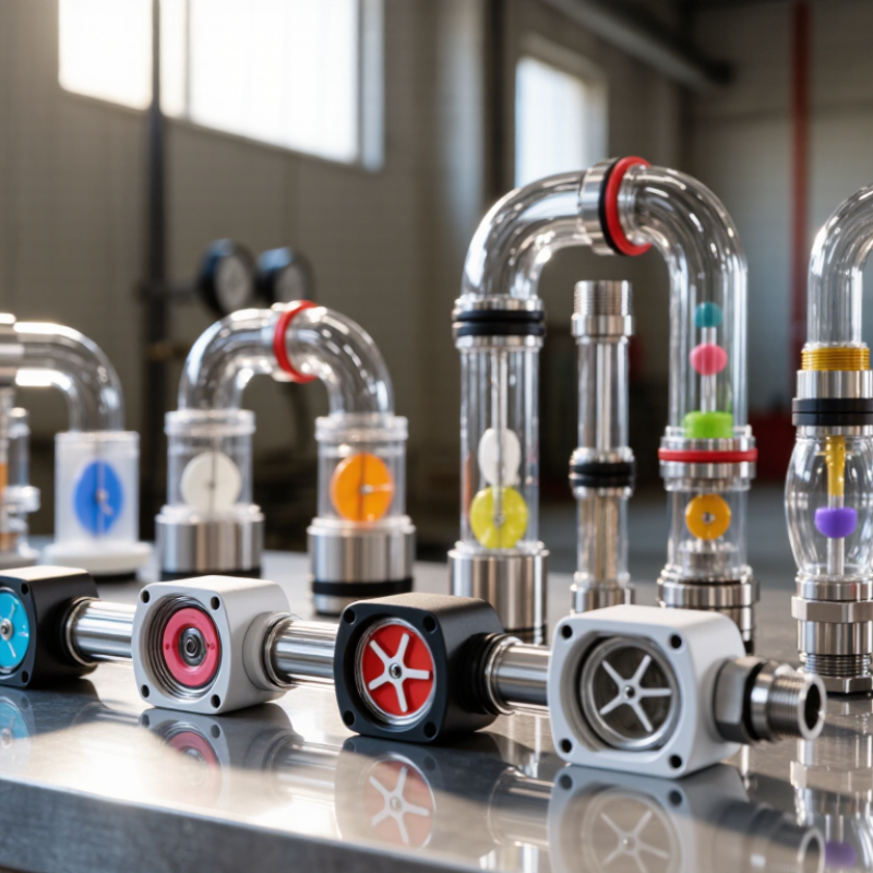
Visual flow indicators are inline devices that show fluid movement through a pipe. They let operators inspect flow without opening the system. A transparent window reveals movement, while an internal rotor, paddle, or flapper responds to the liquid. When flow increases, the moving element turns faster or deflects farther. This creates a quick visual signal, but not always an exact measurement. Some indicators include scales, switches, or sensors for local monitoring.

A sight glass may reveal bubbles, color changes, or unexpected particles. A rotor indicator suits clean fluids with stable viscosity. A flapper design may perform better when minor debris is possible. Simple, but useful.

For global purchasing, buyers should match the indicator to pipe size, fluid chemistry, temperature, pressure, and accuracy requirements. Ask for material certificates, pressure ratings, calibration data, and clear installation instructions. Recognized test reports can support technical claims, but documents still require careful checking.

Arrows on the body must match the actual flow direction. Incorrect orientation can produce a convincing but false reading. Nearby elbows may also disturb the display, especially with short pipe runs. During commissioning, technicians can compare the indicator with a calibrated meter. This may expose scale errors, trapped air, or an unsuitable measurement range.

Readability under low light is easy to overlook. A cloudy window creates uncertainty. I would not treat a bright, moving rotor as proof of correct volume. It only proves visible movement.

Seals, windows, and moving parts need scheduled inspection, with replacement guidance available in the buyer’s region.

Key Types of Visual Flow Indicators for Industrial Systems

10 Best Visual Flow Indicators for Global Buyers

Key Types of Visual Flow Indicators for Industrial Systems

Visual flow indicators let operators confirm movement without opening a pipe or trusting software alone. Sight glass indicators provide direct viewing through a reinforced window. They suit water, oils, and many transparent process fluids. Paddle wheel indicators show movement through a rotating blade. They are simple, but suspended solids can slow or block the paddle.

Rotameters use a floating element inside a calibrated tube. Operators can read approximate flow locally, even during power loss. They require correct installation and a stable vertical position. Target indicators use a spring-loaded disc or flag. They work well where a compact visual check matters more than precise measurement. Magnetic indicators offer a sealed viewing chamber, reducing leakage risks in demanding systems.

Electronic visual indicators combine sensors with a display, alarm, or control signal. They support remote monitoring, but power quality and calibration become important. Bubble or purge indicators help confirm gas flow in low-rate lines. Sanitary sight indicators use smooth internal surfaces for hygienic processing. Temperature, pressure, viscosity, pipe size, and fluid opacity must guide selection.

No indicator is perfect. A clear window may fog. A rotating part may wear. Calibration can also drift unnoticed. During procurement, buyers should request pressure ratings, material certificates, accuracy data, cleaning limits, and installation drawings. One overlooked detail is viewing direction. A technically suitable indicator becomes unreliable when operators cannot see it safely from the working position.

How to Compare the Ten Best Indicators for Global Buyers

Global buyers often compare ten visual flow indicators by asking a simple question: what must be seen, measured, and trusted? In field inspections, I look at visibility first. A clear sight glass shows movement directly, while a rotameter displays approximate flow through a floating element. Paddle-wheel and turbine indicators can provide stronger readings, but they need suitable fluid conditions. Magnetic, ultrasonic, vortex, and Coriolis instruments offer different levels of accuracy and complexity. Each option solves a different problem.

Comparison should include more than price. Check the flow range, pressure rating, temperature limits, connection size, and wetted materials. A buyer handling clean water may accept a basic visual indicator. A chemical process may require corrosion-resistant construction and sealed viewing. For outdoor installations, ingress protection and readable scale markings matter. For international purchasing, request calibration records, test methods, material certificates, and clear operating instructions. These documents reveal product reliability better than polished photographs.

I once focused too heavily on accuracy and overlooked maintenance access. That mistake slowed a replacement project. It was not dramatic, but it was costly. Installation space, spare parts, local technical support, and unit conversion should also shape the decision. A device that performs well in a laboratory may be awkward on a crowded production line. No ranking stays perfect. Buyers should compare actual site conditions, not only catalog specifications. Seeing the flow clearly is useful, but knowing when that view can be misleading is equally important.

10 Best Visual Flow Indicators for Global Buyers

The buyer comparison score combines direct visibility, reading simplicity, application range, maintenance practicality, and documentation availability. The scores are technology-level evaluations and do not represent any company or brand.

Selection Criteria for Pressure, Temperature, Material, and Visibility

10 Best Visual Flow Indicators for Global Buyers

Choosing a visual flow indicator starts with pressure. The housing and sight glass should exceed normal operating pressure and expected surges. ASME B31.3 guidance supports evaluating design pressure, temperature, and fluid compatibility together, not separately. This matters in compressed-air lines, where the U.S. Department of Energy reports that leaks can waste 20–30% of compressor output. A clear window is useless if the seal fails.

Temperature changes the decision. Confirm continuous and peak temperatures, including cleaning cycles and steam exposure. For corrosive or hygienic fluids, wetted materials should match the chemical profile, concentration, and viscosity. Stainless steel is common, but “stainless” is not a complete specification. Gaskets may age first. The IEA’s Energy Efficiency 2023 report identifies industry as responsible for roughly 37% of global final energy demand, so small monitoring errors can become costly across many facilities.

Visibility also requires practical testing. A rotating element, colored paddle, or drip tube should remain readable from the operator’s normal position. Check contrast under low light, vibration, condensation, and dusty conditions. Larger windows improve reading distance, but they may increase pressure drop or maintenance exposure. I have seen perfectly rated indicators installed behind pipe supports. That was technically correct, but operationally poor. Selection should include connection size, flow direction, cleaning access, and local measurement habits. No indicator satisfies every process.

Installation, Maintenance, Standards, and International Purchasing Factors

Selecting the ten best visual flow indicators begins with the pipeline, not the catalog. For clean water, a simple sight glass may provide enough evidence. Opaque fluids often need a float, rotor, or target-style indicator. I have found that readable scale markings matter more than polished housings. Install the device where operators can see it without entering a restricted area. Keep a straight pipe run when the manufacturer specifies one. Avoid mounting near pumps, elbows, and strong vibration. Small errors grow quickly there.

Before installation, verify pressure, temperature, connection size, wetted materials, and flow direction. The indicator should match the medium’s chemistry and expected velocity. Request dimensional drawings, calibration information, pressure-test records, and material certificates. Applicable standards may include ISO, ASME, EN, or local pressure-equipment rules. The exact requirement depends on the destination, industry, and service conditions. Do not treat a familiar standard as universal. That assumption can delay approval. During maintenance, inspect the window, seals, scale, fasteners, and mounting supports. Clean deposits carefully; aggressive tools can scratch viewing surfaces. Record readings before and after cleaning. A cloudy window is a warning.

For international purchasing, compare total landed cost, not unit price alone. Ask about packaging, export documents, spare seals, replacement windows, and technical support. Confirm Incoterms, lead time, inspection points, warranty scope, and after-sales response. Use consistent test conditions when comparing suppliers. A low-cost indicator may need frequent cleaning or early replacement. I once underestimated customs documentation, and the shipment arrived late. That mistake was avoidable. Samples, photographs, and a signed specification reduce misunderstandings across languages. Still, field conditions can defeat a perfect specification. Leave room for operator feedback.

10 Best Visual Flow Indicators for Global Buyers: Installation, Maintenance, Standards, and International Purchasing Factors

Application-based comparison of non-branded visual flow indication technologies for liquid and selected gas services.

No. Indicator Type Visual Principle Best-Fit Application Installation Guidance Maintenance Requirements Common Materials Relevant Standards or References International Purchasing Factors
1 Inline double-window sight flow indicator Flow is observed through two transparent windows; an internal rotor, flapper, or drip element may provide additional movement indication. General liquid lines, cooling water, process water, solvents, and utility systems where direct visual confirmation is required. Install in a straight, accessible section with adequate lighting. Follow the specified flow direction and avoid pipe loads on the body. Confirm flange, threaded, or sanitary-end alignment before tightening. Inspect windows for clouding, scratches, deposits, and leakage. Replace gaskets during planned disassembly and pressure-test the assembly after maintenance. Borosilicate glass or tempered glass; carbon steel, stainless steel, or alloy housing; PTFE, graphite, or elastomer gaskets depending on service. ASME B16.5EN 1092-1DIN 28120PED where applicable Verify flange drilling, pressure class, glass temperature rating, gasket compound, export documentation, and spare-window availability.
2 Rotary wheel flow indicator A paddle wheel or rotor turns when fluid passes, giving a clear visual indication of movement and approximate relative flow. Clean or moderately clean liquids in water treatment, lubrication, cooling, and general industrial piping. Install according to the manufacturer’s orientation limits, normally with the rotor fully wetted. Provide sufficient upstream and downstream straight pipe where required by the design. Check that the wheel rotates freely. Remove scale, fibers, or particulate deposits and inspect the shaft, bearings, window, and seals. Stainless steel, brass, engineering plastics, borosilicate glass, polycarbonate, PTFE, and EPDM or FKM seals. ASME B16.5EN 1092-1IEC 60529 for enclosure claims Confirm minimum starting flow, pressure drop, particle tolerance, wetted-material compatibility, connection standard, and local electrical requirements if switches are included.
3 Flapper or paddle sight flow indicator A hinged flap or paddle moves with the fluid; movement direction and intensity provide a simple go/no-flow indication. Low-to-medium viscosity liquids, lubrication circuits, cooling systems, and pump discharge lines. Install with the arrow matching the process direction. The hinge must move freely, and the selected orientation must support reliable gravity return where applicable. Inspect the hinge, pivot, flap, window, and internal surfaces for wear or fouling. Confirm that the flap returns to its resting position when flow stops. Stainless steel or alloy internals; glass or transparent polymer window; PTFE, graphite, or elastomer sealing elements. ASME B16.5EN 1092-1ISO 5208 for applicable valve-like pressure testing Request the minimum flow needed for visible movement, allowable installation orientation, pressure-temperature curve, and replacement flap or hinge availability.
4 Drip-leg or falling-stream indicator Liquid is viewed as drops or a falling stream through a transparent section, making intermittent or low-rate flow easy to recognize. Condensate return, drain lines, lubrication systems, sampling lines, and low-flow liquid services. Use a vertical downward-flow arrangement when required by the design. Provide drainage, adequate lighting, and protection against accidental impact to the viewing section. Clean the viewing path and drain passages. Check for blocked outlets, condensation, deposits, gasket deterioration, and evidence of external leakage. Borosilicate glass, stainless steel, carbon steel, transparent polymers, PTFE, and chemical-resistant elastomers. DIN 28120 where applicableASME B16.5EN 1092-1 Confirm vertical installation requirements, drain connection size, freezing protection, glass impact protection, and customs classification for the complete assembly.
5 Sanitary clamp sight flow indicator A polished transparent section provides direct observation of product movement while maintaining a hygienic connection. Food, beverage, dairy, pharmaceutical, cosmetic, and other clean-process liquid lines. Install with hygienic alignment and minimal dead space. Use the specified clamp, gasket profile, and surface-finish requirement. Avoid over-tightening, which can damage glass or gaskets. Inspect after each validated cleaning cycle or according to the site schedule. Check gasket compression, glass integrity, product residue, and surface finish. 316L stainless steel, borosilicate glass, PTFE, EPDM, silicone, FKM, or other approved elastomers. ASME BPEISO 2852ISO 2037 where applicable3-A or EHEDG requirements where specified Specify hygienic standard, surface roughness, elastomer approval, clamp dimensions, clean-in-place temperature, sterilization method, and documentation package.
6 Magnetic-coupled visual indicator An internal float or target moves a magnetically coupled external pointer or flag, reducing the need for a dynamic shaft seal. Opaque, corrosive, or hazardous liquids where a sealed visual indication is preferred. Install in the specified vertical or horizontal orientation and keep magnetic components away from strong external magnetic fields. Confirm the process is compatible with the wetted body and float materials. Inspect the external indicator, viewing scale, body seals, and float movement. Remove magnetic or process deposits that could restrict movement. Stainless steel, alloy or lined bodies; glass or transparent cover; PTFE linings; ceramic, stainless steel, or engineered-polymer float components. ASME B16.5EN 1092-1ATEX/IECEx where accessories are installed in hazardous areas Check hazardous-area certification, magnetic compatibility, lining specification, float density, pressure-temperature limits, and language requirements for manuals and markings.
7 Armored sight glass indicator A transparent window is protected by a metal guard, allowing visual flow confirmation in demanding industrial environments. High-temperature utilities, steam condensate, chemical processing, and locations exposed to mechanical impact. Install with the viewing window accessible and the protective cover correctly oriented. Use thermal expansion allowances and insulation practices that do not obscure the view. Inspect the armor, glass, seals, drain or vent features, and corrosion condition. Never operate with cracked, chipped, or severely etched glass. Borosilicate glass, stainless steel, carbon steel, alloy steel, mica shields, graphite, PTFE, and metallic gaskets. DIN 28120ASME B16.5EN 1092-1PED where applicable Evaluate impact protection, thermal shock resistance, pressure-temperature rating, coating or material certificates, and replacement-window lead time.
8 Steam or condensate sight flow indicator A window, rotor, or flapper shows condensate movement and helps identify flow interruption or abnormal two-phase behavior. Steam traps, condensate return, boiler auxiliaries, heat exchangers, and steam distribution systems. Install according to the selected two-phase service design, with correct drainage and flow direction. Protect personnel from hot surfaces and provide isolation where maintenance is required. Check glass condition, flashing or erosion, drain performance, trap operation, and gasket integrity. Inspect more frequently where thermal cycling is severe. Borosilicate glass, carbon steel, stainless steel, alloy steel, graphite, mica, and high-temperature metallic sealing materials. ASME B16.5EN 1092-1ASME B16.34 where valve-body requirements applyPED where applicable Confirm steam pressure and temperature, thermal-shock limits, insulation requirements, flange class, pressure-test records, and regional pressure-equipment compliance.
9 Tank or vessel sight-window indicator A mounted window provides direct observation of liquid level, agitation, color, foam, or movement inside a vessel or reactor. Storage tanks, mixing vessels, reactors, filtration equipment, and process vessels requiring visual inspection. Position the window for safe operator access and adequate illumination. Verify vessel nozzle dimensions, reinforcement, gasket seating, and compatibility with internal pressure or vacuum. Clean the window, inspect fasteners and gaskets, and check for corrosion, stress marks, clouding, or leakage. Follow the vessel owner’s inspection and permit procedures. Borosilicate glass, stainless steel, carbon steel, alloy steel, PTFE, graphite, and sanitary elastomers where applicable. DIN 28120ASME BPVC Section VIII where applicableASME B16.5EN 13445 where applicable Specify vessel code, nozzle size, design pressure and vacuum, operating temperature, glass type, illumination, gasket material, and inspection certification.
10 Multi-directional or universal-view indicator A compact body and large viewing area allow flow observation from several operator positions; an internal element may improve visibility. Skid packages, compact process systems, equipment rooms, and installations where access or viewing angle is restricted. Confirm the permitted orientation before installation. Leave enough clearance for window removal, cleaning, and replacement. Avoid installing directly where vibration or pipe misalignment is excessive. Inspect all viewing surfaces, internal indicator parts, fasteners, and seals. Clean using methods compatible with the glass, coating, and gasket materials. Stainless steel, carbon steel, alloy steel, borosilicate glass, transparent polymers, PTFE, graphite, and elastomers. ASME B16.5EN 1092-1DIN 28120 where applicablePED where applicable Compare overall dimensions, viewing angle, connection standard, vibration resistance, spare-part interchangeability, packaging protection, and multilingual documentation.
Buyer qualification note: Visual flow indicators normally provide qualitative or approximate indication rather than calibrated flow measurement. Final selection must be based on the actual fluid, pressure, temperature, phase, viscosity, solids content, corrosion behavior, pipe size, connection standard, installation orientation, and applicable local safety regulations. Pressure and temperature limits must be confirmed from the supplier’s certified design documentation for the exact configuration.