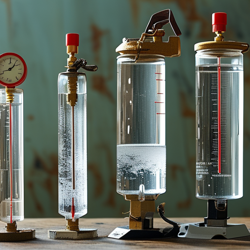
Choosing the right liquid level gauge is not a simple matter of selecting the most expensive model. Each gauge type responds differently to pressure, temperature, fluid properties, and installation conditions. A clear tank of clean water may work well with a sight glass. A sealed chemical vessel may require a magnetic level gauge or radar instrument.
In practical plant inspections, small details often decide whether a gauge performs reliably. Foam can hide the actual liquid surface. Vibration can weaken a float mechanism. Sediment may block a narrow connection. These problems are easy to overlook during specification. They are not minor.
This guide compares the main liquid level gauge types, including sight glass, float, magnetic, ultrasonic, radar, and differential pressure designs. It explains their operating principles, strengths, limitations, and typical applications. The goal is not to declare one universal winner. There is no perfect gauge for every tank. The best choice depends on accuracy requirements, fluid behavior, tank geometry, maintenance access, and operating risk.
Real-world experience also shows that installation quality matters as much as product selection. A well-designed gauge can still provide poor readings when mounted incorrectly. Even reliable instruments need inspection and occasional calibration. That point deserves attention. By examining each option carefully, readers can avoid common purchasing mistakes and choose a level measurement solution with greater confidence.
A liquid level gauge shows how much fluid is inside a tank, vessel, or process line. It gives operators a direct reading without opening the container. Some gauges use a float that rises and falls with the liquid. Others use a transparent sight tube, magnetic indicator, or electronic sensor. The operating principle is simple: liquid movement changes a visible position or measured signal. Small details matter, though. Density, temperature, pressure, and fluid cleanliness can affect accuracy.
Tips: Match the gauge to the liquid and tank conditions. For thick fluids, a narrow sight tube may become difficult to read. A float gauge can work well, but buildup may restrict movement. Check the scale from eye level. Parallax causes surprisingly common errors. Inspect seals and connections regularly, especially where temperature changes are frequent.
Different liquid level gauge types suit different work. Sight gauges offer clear visual confirmation, while magnetic gauges improve visibility when the liquid is dark or hazardous to view directly. Electronic gauges support remote monitoring, but they need correct calibration and reliable power. No gauge is perfect. A practical selection compares accuracy, maintenance, pressure rating, installation space, and failure behavior. In my experience, the “best” gauge is the one operators can read quickly and verify easily. Fancy equipment can still disappoint when the display is poorly placed.
Liquid level gauges usually fall into several practical groups. Sight glass gauges offer direct visual confirmation through a glass tube or armored window. Float and displacer gauges measure changing buoyancy, making them useful for tanks with steady liquids. Hydrostatic gauges calculate level from pressure at the tank bottom. They work well, but density changes can create errors.
Ultrasonic gauges send sound pulses from above the liquid. They are non-contact and suit corrosive fluids, although foam, vapor, or heavy turbulence may weaken the signal.
Radar gauges also measure without contact. They generally handle vapor and pressure better, but installation geometry matters.
Capacitive gauges detect changes in electrical capacitance. Vibrating-fork switches provide simple high- or low-level alarms, rather than continuous measurement. According to the 2024 MarketsandMarkets Level Sensor Market report, the sector is projected to grow from about USD 4.5 billion in 2023 to nearly USD 6.0 billion by 2028. That growth reflects wider automation, not one universally superior gauge.
Tips: Match the gauge with liquid density, temperature, pressure, foam, and tank shape. Check the process connection before ordering. Keep a manual sight indicator when safe and practical. It can reveal a failed transmitter quickly. Still, that choice is not perfect. A dirty window can mislead operators, while a digital sensor may hide installation problems. Test the selected device under realistic conditions, including an almost empty tank and a near-full tank.
Top Liquid Level Gauge Types: Which One Is Best?
Accuracy and reliability depend on the liquid, tank design, and operating conditions. A sight glass offers direct visual confirmation, but dirty fluids can hide the reading. Float gauges are simple and economical. However, foam, turbulence, or changing liquid density may affect their movement. Magnetic gauges isolate the indicator from the process fluid, improving safety and readability. They still require careful installation and periodic inspection.
Radar gauges usually provide strong accuracy in tall tanks, even when pressure or temperature changes. Ultrasonic gauges can work well without contact, but vapour, foam, and tank obstructions may distort their signals. In field service, a stable reading matters as much as a precise specification. A gauge that reads accurately only in ideal conditions may disappoint operators. Some readings still drift. That is worth acknowledging.
Tips: Match the gauge to the liquid’s viscosity, temperature, density, and chemical behaviour. Check the stated accuracy across the full measuring range, not at one test point. Keep sensing surfaces clean and compare readings with a trusted reference during maintenance. Record unusual fluctuations instead of adjusting the instrument immediately. A loose connection, trapped air, or vibration may be the real cause. When selecting equipment, review installation drawings and test records with a qualified technician. The best choice is not always the most advanced one.
Liquid level gauges differ mainly in accuracy, contact with the process, and resistance to foam, vapor, pressure, temperature, and changing fluid properties. The chart compares typical accuracy ranges and a practical reliability score for common level measurement technologies.
Accuracy is shown as the typical maximum error percentage of measuring span, where a lower value is better. Reliability is a comparative 1–10 index based on resistance to common installation and process disturbances; actual performance depends on application conditions, installation quality, calibration, and maintenance.
Choosing the best liquid level gauge starts with the process, not the product list. A clear water tank may work well with a sight glass or float gauge. However, dark, corrosive, or foaming liquids can hide the reading. Fluid density, viscosity, temperature, and vapor pressure directly affect measurement reliability. Small details matter.
Tank design also changes the answer. A narrow vessel may need a compact instrument, while a tall tank demands a wider measurement range. High pressure and extreme heat require strong materials and carefully rated connections. For non-contact measurement, radar or ultrasonic gauges can reduce maintenance. Yet foam, vapors, and internal obstructions may weaken their signals. Real installations are rarely as clean as drawings suggest.
Accuracy is only one factor. Operators should consider visibility, response speed, cleaning access, calibration needs, and failure behavior. A gauge that gives a fast reading may still be unsuitable if workers cannot inspect it safely. In my experience, maintenance teams often value simple mechanical indicators more than designers expect. I have also seen apparently correct selections fail after temperature changes were overlooked. That mistake is worth revisiting. Check the fluid data, mounting position, pressure rating, and applicable safety requirements before approval. Independent testing and documented calibration provide stronger evidence than a catalog claim. The best gauge is the one that remains readable, stable, and serviceable under actual operating conditions.
Top Liquid Level Gauge Types: Which One Is Best?
Correct installation determines whether a liquid level gauge remains trustworthy. A 2024 market report by Grand View Research valued the global level sensor market at approximately USD 5.4 billion in 2023. Growth reflects wider automation, but more devices do not guarantee better readings. Choose a sight glass for direct visual checks, a float gauge for simple tanks, or a radar gauge for corrosive, high-temperature, or closed vessels. Confirm process pressure, temperature, density, viscosity, and chemical compatibility before purchase. I have seen accurate gauges fail because the connection size was treated as an afterthought.
Mount the gauge where operators can read it safely, away from filling turbulence and heavy vibration. Install isolation valves and a drain connection when process design permits. Keep the sensing path vertical and free from sludge, crystallization, and trapped air. For radar equipment, check the beam path for ladders, coils, and internal supports. Calibration should follow the manufacturer’s procedure and the site’s risk assessment. The International Society of Automation recommends lifecycle-based maintenance for safety-related systems, yet field teams often inspect only after a visible fault. That habit needs reconsideration.
Tips: Record the initial zero, reference level, ambient temperature, and calibration date. Compare the gauge with an independent measurement during scheduled rounds. Clean sight glasses carefully; small scratches can distort readings. Replace damaged seals immediately. Do not trust a stable reading without checking the process conditions.
| Gauge Type | Operating Principle | Typical Applications | Typical Accuracy | Main Advantages | Main Limitations | Best Choice When |
|---|---|---|---|---|---|---|
| Sight Glass Gauge | The liquid level is viewed directly through a transparent tube or glass window connected to the vessel. | Water, oils, non-hazardous liquids, tanks requiring local visual indication. | Visual indication; commonly read to approximately 5–10 mm depending on scale and installation. | Simple, low operating cost, no electrical power, easy to understand. | Requires line of sight; glass can become cloudy, stained, damaged, or unsuitable for some hazardous services. | A local, low-cost visual reading is sufficient. |
| Float and Board Gauge | A float follows the liquid surface and moves a pointer, tape, or external indicator. | Large atmospheric storage tanks containing relatively clean liquids. | Typically about 1–2% of full scale, depending on mechanical design and tank conditions. | Easy local reading, independent of liquid conductivity, and suitable for large tanks. | Moving parts may stick; wind, cable friction, tank turbulence, and buildup can affect the reading. | A simple level display is needed on a large, non-pressurized tank. |
| Magnetic Level Gauge | A float with an internal magnet moves inside a chamber and turns external colored flags or a pointer. | Pressurized vessels, boilers, chemical tanks, and applications requiring a clear local display. | Commonly approximately ±5–10 mm, subject to chamber length and float selection. | Good visibility, isolated process fluid, no glass in direct contact with the liquid, and optional switches or transmitters. | The chamber and float must match liquid density, pressure, temperature, and viscosity; deposits can restrict movement. | A reliable local indication is required for a pressurized or hazardous vessel. |
| Hydrostatic Pressure Gauge | Measures pressure created by the liquid column and converts it to level using liquid density. | Water, wastewater, sumps, wells, and tanks with stable liquid density. | Often approximately ±0.25–1% of full scale for suitable pressure transmitters. | Works in opaque liquids, unaffected by surface foam in many installations, and supports remote monitoring. | Accuracy changes with density, temperature, vapor pressure, blocked impulse lines, or incorrect zero reference. | The liquid density is known or controlled and continuous remote measurement is needed. |
| Ultrasonic Level Gauge | Emits sound pulses and calculates level from the return time of the echo from the liquid surface. | Open channels and tanks containing water, wastewater, and many non-volatile liquids. | Commonly about ±0.25–0.5% of measured range under suitable conditions. | Non-contact measurement, minimal wetted maintenance, and straightforward digital integration. | Foam, vapor, condensation, turbulence, obstructions, and temperature changes can weaken or distort echoes. | The tank is vented and the surface is relatively calm with limited vapor or foam. |
| Radar Level Gauge | Uses microwave pulses and measures the time or frequency shift of the signal reflected by the liquid surface. | Process tanks, storage tanks, corrosive liquids, high-temperature services, and vessels with vapor or pressure. | Often approximately ±2–10 mm, depending on technology, antenna, installation, and process conditions. | Non-contact, largely independent of liquid density and temperature, and generally more tolerant of vapor than ultrasonic devices. | Higher initial cost; internal structures, heavy coating, weak dielectric liquids, or poor positioning can affect the signal. | High reliability and accuracy are required in a difficult process environment. |
| Capacitance Level Gauge | Detects changes in electrical capacitance between a probe and the vessel wall or a reference electrode. | Powders, granules, conductive liquids, and some interface or point-level applications. | Application-dependent; typically about ±1–2% of full scale after proper calibration. | Compact, suitable for continuous or point-level detection, and available for high-temperature applications. | Probe coating, changing dielectric properties, moisture, and buildup can cause measurement drift. | The material properties are stable and probe buildup can be controlled. |
| Installation Requirements | ||||||
| Installation Item | Recommended Practice | Reason | Common Risk if Ignored | |||
| Connection and Isolation | Use correctly rated process connections, gaskets, valves, and fittings. Provide isolation and drain or vent provisions where required. | Supports safe inspection, removal, and pressure testing. | Leaks, uncontrolled release, or unsafe maintenance. | |||
| Measurement Reference | Define the zero and span points clearly, and verify the instrument range against the actual tank bottom and maximum operating level. | Prevents incorrect level readings and alarm settings. | Displayed level may not match the actual liquid volume. | |||
| Sensor Position | Keep sensors away from inlet streams, agitators, ladders, heating coils, stiffeners, and other obstructions. Follow the required clearance for the selected technology. | Reduces turbulence, false echoes, splashing, and mechanical interference. | Unstable, intermittent, or biased readings. | |||
| Environmental Protection | Check temperature, pressure, corrosion, vibration, hazardous-area requirements, ingress protection, and electromagnetic interference before installation. | Ensures the gauge remains within its rated operating conditions. | Premature failure, unsafe operation, or inaccurate output. | |||
| Electrical and Signal Wiring | Use the correct power supply, grounding, cable routing, shielding, and signal termination. Confirm polarity and output configuration. | Protects signal quality and enables reliable control-system communication. | Noise, signal loss, incorrect readings, or equipment damage. | |||
| Maintenance Schedule and Actions | ||||||
| Frequency | Maintenance Action | Applicable Gauge Types | Acceptance Check | |||
| Each Operating Shift or Daily | Check the displayed level, alarms, visible leakage, unusual vibration, and obvious damage. | All types | Reading is stable and consistent with process conditions; no unsafe leakage or damage is present. | |||
| Monthly or Quarterly | Clean sight glasses, inspect magnetic flags and floats, check impulse lines, examine cable glands, and review diagnostic messages. | Visual, float, magnetic, hydrostatic, ultrasonic, radar, and capacitance gauges | No sticking, blockage, coating, condensation, loose connection, or unexplained diagnostic fault. | |||
| Six Months to One Year | Compare the gauge with an independent reference measurement and test alarms, switches, outputs, and interlocks. | All types, subject to process criticality | Deviation remains within the site-approved tolerance and all protective functions operate correctly. | |||
| After Process or Instrument Changes | Recheck calibration and configuration after changing liquid density, temperature, tank geometry, nozzle position, software, or process conditions. | Especially hydrostatic, radar, ultrasonic, and capacitance gauges | The measurement range, calibration, and alarm setpoints remain appropriate for the revised service. | |||
| Selection Summary: A sight glass or float gauge is generally suitable for simple local indication. A magnetic gauge is preferred when a clear local reading is needed on a pressurized vessel. Hydrostatic measurement is effective for remote monitoring of liquids with stable density. Ultrasonic gauges suit many vented tanks with calm surfaces, while radar gauges are often the strongest choice for demanding conditions involving vapor, pressure, temperature, or changing process conditions. The final selection must be verified against pressure, temperature, liquid properties, tank geometry, hazardous-area requirements, and the applicable site or industry standards. | ||||||